Assignment 2: Create a new project with Components
In this assignment, we will show how to work with Components and how to use them to speed up the development of your projects.
Components are similar to libraries (like those from Arduino IDE); they also contain various additional functionality that you wouldn’t find in basic ESP-IDF. For example, let’s mention various drivers for sensors, protocol components, or BSP (board support package) components. Some components are already a direct part of some ESP-IDF examples, but it is also possible to use external components thanks to the modular structure of ESP-IDF.
By using components, not only is project maintainability simplified, but its development is also significantly accelerated. Components also allow the same functionality to be reused across different projects.
If you want to create and publish your own component (for example for your specific sensor), we recommend that you watch the talk DevCon23 - Developing, Publishing, and Maintaining Components for ESP-IDF:
You can browse components, for example, through the ESP Registry platform.
We will demonstrate the use of components on a new project, where we will write a simple application from scratch that will blink the built-in RGB LED using a component for LED strips.
Working with components
We will use the following two components:
- Component for RGB LED (WS2812) strips, although in our case the LED “strip” will be only a
single built-in LED connected to
GPIO27. - Remote Control Transceiver (RMT) component, which we will use to control the data flow to the LED.
- Creating a new project
A new project can be created via GUI or command line. For those who don’t work much with terminal (CLI), it can be somewhat scary, but in the future it will help you, for example, in situations where you will use ESP-IDF with an IDE other than VSCode (or completely standalone). Both examples are given below.
GUI
Open ESP-IDF Explorer (Espressif icon in taskbar or via View -> Open View -> ESP-IDF: Explorer) and select New Project Wizard command (may be hidden in Advanced menu). Then proceed according to the pictures:
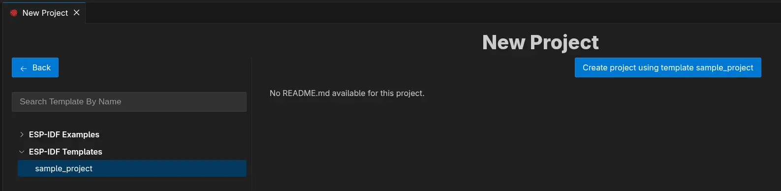
Creating a new project. Serial port is not important, it can be changed later.
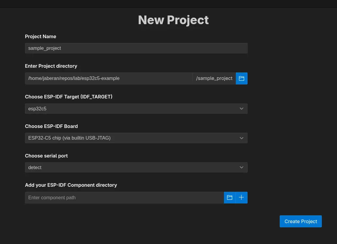
In the next step we choose what template to base our project on. We choose *get-started/hello_world and create the project.*
After creating the project, an unobtrusive window will appear in the bottom right, which will ask you whether you want to open the newly created project in a new window. Click “Yes”.
CLI
In the ESP-IDF Explorer in the commands tab, select ESP-IDF Terminal, which will open at the bottom of the screen. To create a new project:
- Create and go to the folder where we want to have our project
- Create the project
- Go to it
mkdir ~/my-workshop-folder
cd ~/my-workshop-folder
idf.py create-project my-workshop-project
cd my-workshop-project
If the
idf.py ...commands don’t work for you, make sure you’re using ESP-IDF Terminal and not just a regular console.
Now we need to set the so-called target. This word can have multiple meanings in the context of ESP-IDF, but in our case it will always mean the type of SoC we are using. In our case it is ESP32-C5 chip (via Builtin USB JTAG).
In CLI there is a slight problem, as there may be a mismatch between VSCode and ESP-IDF, so it is better to set an environment variable instead of a command.
export IDF_TARGET=esp32c5
# idf.py set-target esp32c5
Now we are ready to add the espressif/led_strip component. As already mentioned, the component will take care of all the necessary drivers for our LED “strip” with one built-in diode.
- Adding a component
GUI
- Open View -> Command Palette (Ctrl + Shift + P or ⇧ + ⌘ + P) and type ESP-IDF: Show ESP Component Registry in the newly opened line. Now search for espressif/led_strip (searching may take a few seconds when seemingly nothing happens), click on the component, select the correct version (3.0.3) and click Install.
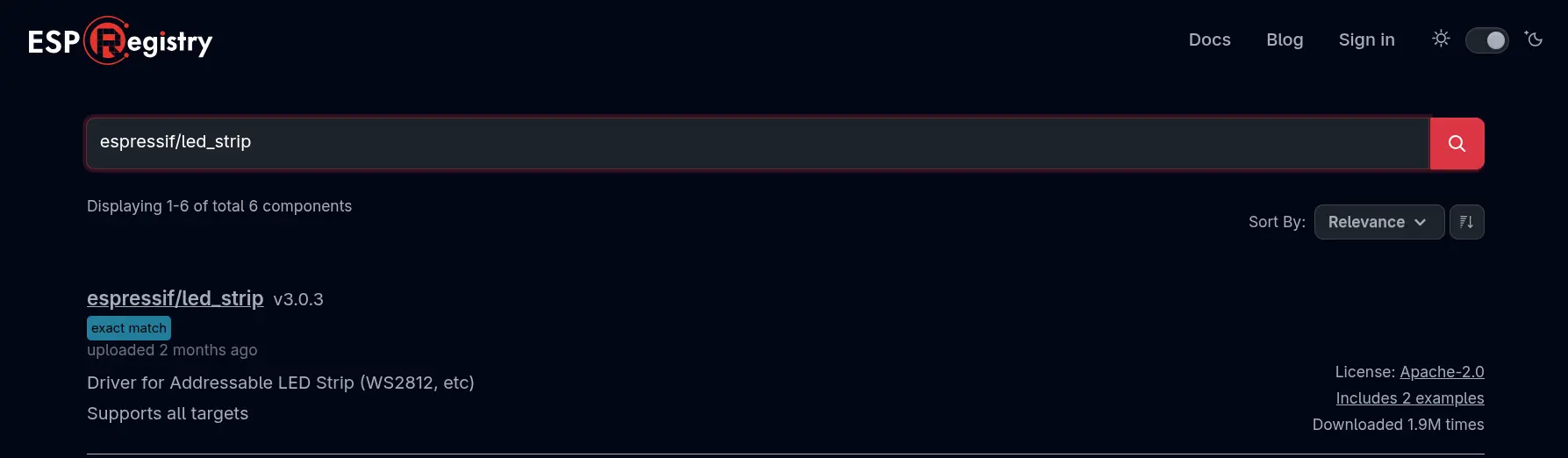
Component search
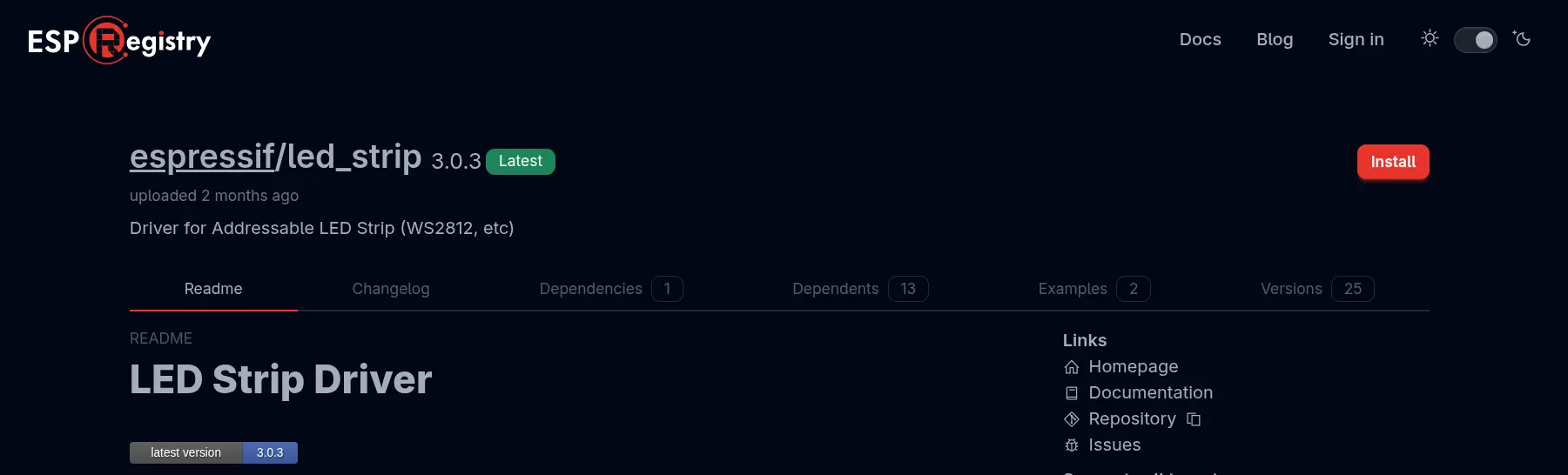
Component installation
CLI
idf.py add-dependency "espressif/led_strip^3.0.3"
You may notice that a new file named idf_component.yml has been created in the main project directory (main). On the first build, the managed_components folder will also be created and the component will be downloaded to it if it was added via CLI. If you added the component via GUI, everything will be created even without build.
# Contents of idf_component.yml
dependencies:
  espressif/led_strip: "^3.0.3"
  idf:
    version: ">=4.4"
You can also add dependent components to this file manually, without using any commands.
Now we will throw ourselves into the programming itself.
- Creating a function that configures the LED and RMT driver
Let’s open the file main.c. First we need to import the necessary libraries…
#include "led_strip.h"
#include "esp_log.h"
#include "esp_err.h"
…declare the necessary constants and the logging tag…
// 10MHz resolution, 1 tick = 0.1us (led strip needs a high resolution)
#define LED_STRIP_RMT_RES_HZ  (10 * 1000 * 1000)

static const char *TAG = "led_strip";
…and create a function skeleton for configuration. The function returns the LED strip handle,
which we will use in app_main:
led_strip_handle_t configure_led(void)
{
    led_strip_handle_t led_strip;
    // Your code goes here
    return led_strip;
}
You will write the following steps into this function in place of the comment Your code goes here.
- LED “strip” configuration
We use the led_strip_config_t structure. For ESP32-C5-DevKit-C, the LED is of type WS2812.
    led_strip_config_t strip_config = {
        // Set the GPIO that the LED is connected
        .strip_gpio_num = 27,
        // Set the number of connected LEDs, 1
        .max_leds = 1,
        // Set the pixel format of your LED strip
        .color_component_format = LED_STRIP_COLOR_COMPONENT_FMT_GRB,
        // LED model
        .led_model = LED_MODEL_WS2812,
        // In some cases, the logic is inverted
        .flags.invert_out = false,
    };
- RMT configuration
We use the led_strip_rmt_config_t structure:
    led_strip_rmt_config_t rmt_config = {
        // Set the clock source
        .clk_src = RMT_CLK_SRC_DEFAULT,
        // Set the RMT counter clock
        .resolution_hz = LED_STRIP_RMT_RES_HZ,
        // Set the memory block size (0 means let driver choose automatically)
        .mem_block_symbols = 0,
        // Set the DMA feature (not supported on the ESP32-C5)
        .flags.with_dma = false,
    };
- Creating RMT device
We call led_strip_new_rmt_device() wrapped in ESP_ERROR_CHECK() — if initialisation fails,
the program halts immediately with an error message. On success we log the result and return the
handle:
    ESP_ERROR_CHECK(led_strip_new_rmt_device(&strip_config, &rmt_config, &led_strip));
    ESP_LOGI(TAG, "LED strip initialized successfully");
    return led_strip;
- Creating an object for the LED “strip”
When we have the configure_led() function ready, we call it in the main app_main function and
store the returned handle in a local variable:
led_strip_handle_t led_strip = configure_led();
- Setting colors
To set the color, we use the led_strip_set_pixel function with the following parameters:
led_strip: our configured LED “strip” object0: diode index in the strip (since we only have one, the index will always be 0)20: red (RED) component with values between 0 and 2550: green (GREEN) component with values between 0 and 2550: blue (BLUE) component with values between 0 and 255
ESP_ERROR_CHECK(led_strip_set_pixel(led_strip, 0, 20, 0, 0));
Try different values for R,G,B channels!
- Update LED “strip” values
Just setting the pixel value is not enough; for the values set in the previous step to take effect, the entire “strip” must first be refreshed:
    ESP_ERROR_CHECK(led_strip_refresh(led_strip));
    ESP_LOGI(TAG, "LED strip set to red and refreshed");
If we want to turn off the entire LED strip, we can use the function led_strip_clear(led_strip);.
- Building and uploading code to the board
When our code is complete, we need to somehow get it into our board. The entire process can be divided into 4 steps:
- Determining the target: the specific board we are using. In the ESP-IDF explorer tab in the Commands section, select Set Espressif Device Target (IDF_TARGET), choose esp32c5 and in the subsequent menu select ESP32-C5 chip (via builtin USB-JTAG).
- Build: building the application and creating a binary file that we will upload. In the same place as last time, click on the Build Project command.
- Selecting the correct serial port to which our board is connected. We also set the serial port using a command in ESP-IDF Explorer, this time using Select Port to Use.
- Flash: uploading the binary file to the board. The command of the same name will serve us for this, which can be found right next to the others. If VScode asks us about “flash method”, we select “UART”.
If someone accidentally selects the wrong flash method (e.g. JTAG), just manually edit
"idf.flashType": to "UART" in the .vscode/settings.json file.
All commands can also be invoked using Command Palette, which you open with the key combination Ctrl + Shift + P or ⇧ + ⌘ + P. However, the commands are sometimes named slightly differently (for example, instead of Select Serial Port, the command is called ESP-IDF: Select Port to Use). You can freely combine both approaches.
Complete code
Below you can find the complete and commented code for this assignment:
#include <stdio.h>
#include "led_strip.h"
#include "esp_log.h"
#include "esp_err.h"

// 10MHz resolution, 1 tick = 0.1us (led strip needs a high resolution)
#define LED_STRIP_RMT_RES_HZ  (10 * 1000 * 1000)

static const char *TAG = "led_strip";

led_strip_handle_t configure_led(void)
{
    // LED strip general initialization, according to your led board design
    led_strip_config_t strip_config = {
        .strip_gpio_num = 27,
        .max_leds = 1,
        .color_component_format = LED_STRIP_COLOR_COMPONENT_FMT_GRB,
        .led_model = LED_MODEL_WS2812,
        .flags.invert_out = false,
    };

    // LED strip backend configuration: RMT
    led_strip_rmt_config_t rmt_config = {
        .clk_src = RMT_CLK_SRC_DEFAULT,
        .resolution_hz = LED_STRIP_RMT_RES_HZ,
        .mem_block_symbols = 0,
        .flags.with_dma = false,
    };

    // LED Strip object handle
    led_strip_handle_t led_strip;
    ESP_ERROR_CHECK(led_strip_new_rmt_device(&strip_config, &rmt_config, &led_strip));
    ESP_LOGI(TAG, "LED strip initialized successfully");
    return led_strip;
}

void app_main(void)
{
    led_strip_handle_t led_strip = configure_led();
    ESP_ERROR_CHECK(led_strip_set_pixel(led_strip, 0, 20, 0, 0));
    ESP_ERROR_CHECK(led_strip_refresh(led_strip));
    ESP_LOGI(TAG, "LED strip set to red and refreshed");
}
Expected result
The built-in LED should light up red.
Info: The generic BSP component espressif/esp_bsp_generic (version 1.2.0) does not currently support the ESP32-C5, so the BSP-based approach is not covered in this workshop. If you are interested in BSP usage, refer to the ESP32-C6 version of this workshop.
Next step
Let there be light! When we can do basic tasks with ESP and IDE, we are ready to connect to WiFi too!