Lecture: ESP-IDF introduction
Info: Compared to the ESP32-C6 version of this workshop, the ESP32-C5 track intentionally skips the dedicated protocols/TLS chapter. If you want to explore that topic in depth, use the ESP-IDF examples, esp-protocols, or the ESP32-C6 workshop.
The ESP-IDF (Espressif IoT Development Framework) is the official operating system and development framework for the ESP32 series of microcontrollers by Espressif Systems. It provides a comprehensive environment for building IoT applications with robust networking, security, and reliability features.
ESP-IDF framework includes FreeRTOS that allows developers to create real-time, multitasking applications. With extensive libraries, components, protocols, tools, and documentation, ESP-IDF simplifies the development process enabling seamless integration with hardware peripherals, such as Wi-Fi, Bluetooth, Thread, ZigBee, and cloud services.
ESP-IDF includes almost 400 examples, covering a wide range of use cases and helping developers quickly get started on their projects.
Architecture
The ESP-IDF platform architecture is mainly divided into 3 layers:
- ESP-IDF platform
- Contains the core components required and all the operating system. Includes the FreeRTOS, drivers, build system, protocols, etc.
- Middleware
- Adds new features to the ESP-IDF, for example the audio framework and HMI.
- AIoT Application
- This is your application.
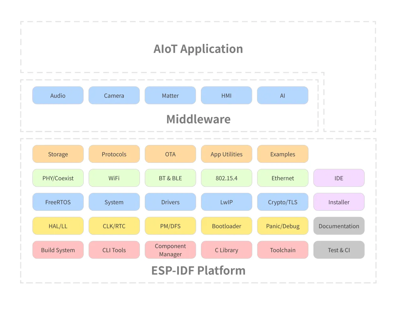
All the necessary blocks for building your application will be included on the ESP-IDF platform.
Frameworks
Several other frameworks use ESP-IDF as a base, including:
- Arduino for ESP32
- ESP-ADF (Audio Development Framework): Designed for audio applications.
- ESP-WHO (AI Development Framework): Focused on face detection and recognition.
- ESP-RainMaker: Simplifies building connected devices with cloud capabilities.
- ESP-Matter SDK: Espressif’s SDK for Matter is the official Matter development framework for ESP32 series SoCs.
To see all the supported frameworks, please visit our GitHub organization page.
Current supported versions
Visit the ESP-IDF project on GitHub to get the updated list of supported versions and the maintenance period.
Introduction to the ESP32-C5
The ESP32-C5 is a Ultra-low-power SoC with RISC-V single-core microprocessor, 2.4 GHz Wi-Fi 6 (802.11ax), Bluetooth® 5 (LE), Zigbee and Thread (802.15.4). It has an optional 4 MB flash in the chip’s package, 30 or 22 GPIOs, rich set of peripherals including:
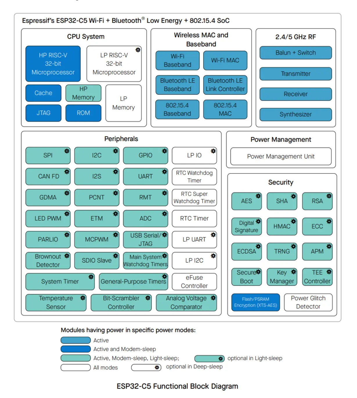
- 30 GPIOs (QFN40), or 22 GPIOs (QFN32)
- 5 strapping GPIOs
- 6 GPIOs needed for in-package flash
- Analog interfaces:
- 12-bit SAR ADC, up to 7 channels
- Temperature sensor
- Digital interfaces:
- Two UARTs
- Low-power (LP) UART
- Two SPI ports for communication with flash
- General purpose SPI port
- I2C
- Low-power (LP) I2C
- I2S
- Pulse count controller
- USB Serial/JTAG controller
- Two TWAI® controllers, compatible with ISO 11898-1 (CAN Specification 2.0)
- SDIO 2.0 slave controller
- LED PWM controller, up to 6 channels
- Motor Control PWM (MCPWM)
- Remote control peripheral (TX/RX)
- Parallel IO interface (PARLIO)
- General DMA controller, with 3 transmit channels and 3 receive channels
- Event task matrix (ETM)
- Timers:
- 52-bit system timer
- Two 54-bit general-purpose timers
- Three digital watchdog timers
- Analog watchdog timer
For more details, please see the product ESP32-C5 Datasheet.
Wi-Fi 6 (IEEE 802.11ax)
Wi-Fi 6, also known as IEEE 802.11ax, represents the latest generation of Wi-Fi technology, designed to improve efficiency, capacity, and performance in various environments. Key features of Wi-Fi 6, as seen in devices like the ESP32-C5, include:
- 20 MHz-only Non-AP Mode: This mode operates in a non-access point capacity, utilizing a 20 MHz channel width.
- MCS0 ~ MCS9: Support for modulation and coding schemes ranging from MCS0 to MCS9, which dictate data rates and signal robustness.
- Uplink and Downlink OFDMA: Orthogonal Frequency Division Multiple Access enables efficient simultaneous connections, particularly beneficial in high-density environments.
- Downlink MU-MIMO: Multi-user, multiple input, multiple output technology increases network capacity by allowing the transmission of data to multiple devices at the same time.
- Beamforming: This feature enhances signal quality by focusing the Wi-Fi signal towards the receiving device.
- Channel Quality Indication (CQI): Provides real-time feedback on the channel conditions, aiding in dynamic adjustments for optimal performance.
- DCM (Dual Carrier Modulation): Enhances link robustness by using dual carriers.
- Spatial Reuse: Maximizes parallel transmissions by allowing multiple devices to communicate simultaneously on the same frequency without significant interference.
- Target Wake Time (TWT): Optimizes power-saving mechanisms by scheduling specific times for devices to wake up and communicate, extending battery life.
Wi-Fi MAC support for the 802.11ax:
- Target wake time (TWT) requester
- Multiple BSSIDs
- Triggered response scheduling
- Uplink power headroom
- Operating mode
- Buffer status report
- Multi-user Request-to-Send (MU-RTS), Multi-user Block ACK Request (MU-BAR), and Multi-STA Block ACK (M-BA) frame
- Intra-PPDU power saving mechanism
- Two network allocation vectors (NAV)
- BSS coloring
- Spatial reuse
- TXOP duration RTS threshold
- UL-OFDMA random access (UORA)
Resources
Introduction to the ESP32-C5-DevKit-C
The ESP32-C5-DevKitC-1 is a beginner-friendly development board featuring the ESP32-C5-WROOM-1(U) module, which includes an 8 MB SPI flash. This board offers comprehensive Wi-Fi, Bluetooth LE, Zigbee, and Thread capabilities.
To facilitate easy interfacing, most of the I/O pins are accessible through pin headers on both sides. Developers can connect peripherals using jumper wires or mount the ESP32-C5-DevKitC-1 on a breadboard.
Features
Here is the development board feature list:
- ESP32-C5-WROOM-1 module
- Pin Header
- 5 V to 3.3 V LDO
- 3.3 V Power On LED
- USB-to-UART Bridge
- ESP32-C5 USB Type-C Port for flashing and debug
- Boot Button
- Reset Button
- USB Type-C to UART Port
- RGB LED connected to the GPIO8
- J5 jumper used for current measurement.
Board description
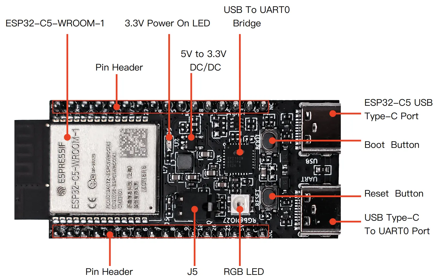
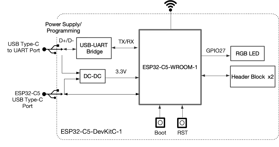
Board pin-layout
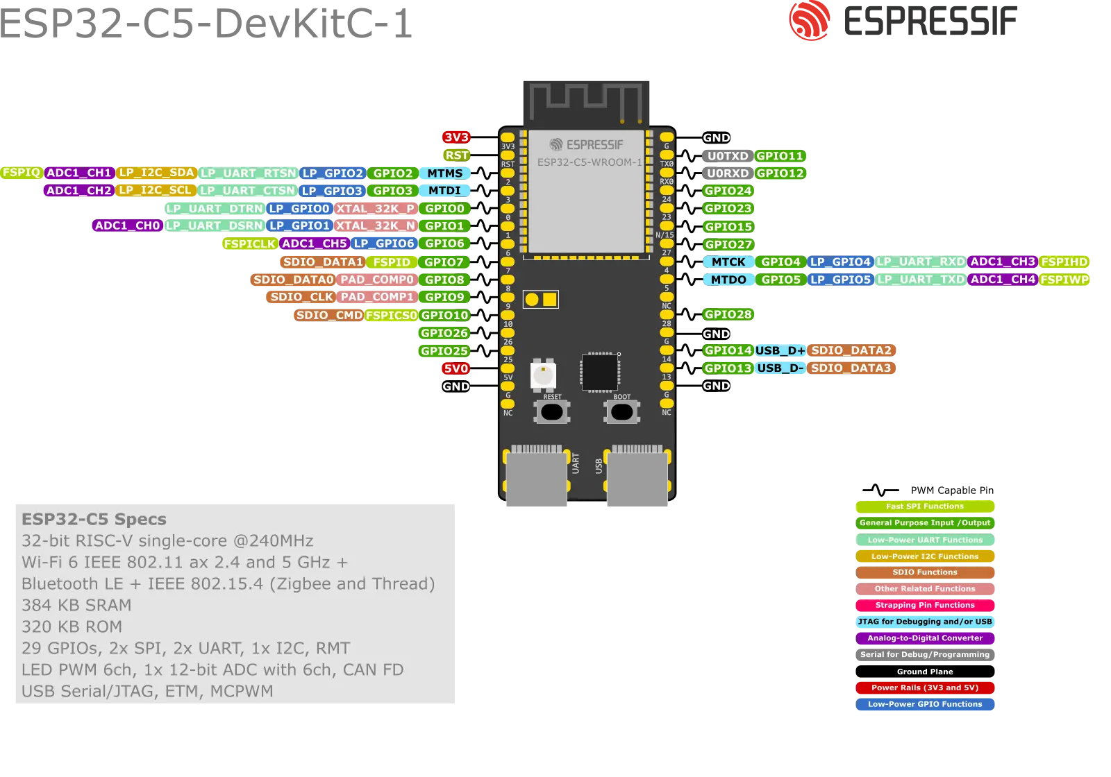
J1 connector
| No. | Name | Type | Function |
|---|---|---|---|
| 1 | 3V3 | P | 3.3 V power supply |
| 2 | RST | I | High: enables the chip; Low: disables the chip. |
| 3 | 2 | I/O/T | MTMS, GPIO2, LP_GPIO2, LP_UART_RTSN, LP_I2C_SDA, ADC1_CH1, FSPIQ |
| 4 | 3 | I/O/T | MTDI, GPIO3, LP_GPIO3, LP_UART_CTSN, LP_I2C_SCL, ADC1_CH2 |
| 5 | 0 | I/O/T | GPIO0, XTAL_32K_P, LP_GPIO0, LP_UART_DTRN |
| 6 | 1 | I/O/T | GPIO1, XTAL_32K_N, LP_GPIO1, LP_UART_DSRN, ADC1_CH0 |
| 7 | 6 | I/O/T | GPIO6, LP_GPIO6, ADC1_CH5, FSPICLK |
| 8 | 7 | I/O/T | GPIO7, FSPID, SDIO_DATA1 |
| 9 | 8 | I/O/T | GPIO8, PAD_COMP0, SDIO_DATA0 |
| 10 | 9 | I/O/T | GPIO9, PAD_COMP1, SDIO_CLK |
| 11 | 10 | I/O/T | GPIO10, FSPICS0, SDIO_CMD |
| 12 | 26 | I/O/T | GPIO26 |
| 13 | 25 | I/O/T | GPIO25 |
| 14 | 5V | P | 5 V power supply |
| 15 | G | G | Ground |
| 16 | NC | – | No connection |
J3 connector
| No. | Name | Type | Function |
|---|---|---|---|
| 1 | G | G | Ground |
| 2 | TX | I/O/T | U0TXD, GPIO11 |
| 3 | RX | I/O/T | U0RXD, GPIO12 |
| 4 | 24 | I/O/T | GPIO24 |
| 5 | 23 | I/O/T | GPIO23 |
| 6 | NC/15 | I/O/T | No connection/GPIO15 |
| 7 | 27 | I/O/T | GPIO27 |
| 8 | 4 | I/O/T | MTCK, GPIO4, LP_GPIO4, LP_UART_RXD, ADC1_CH3, FSPIHD |
| 9 | 5 | I/O/T | MTDO, GPIO5, LP_GPIO5, LP_UART_TXD, ADC1_CH4, FSPIWP |
| 10 | NC | – | No connection |
| 11 | 28 | I/O/T | GPIO28 |
| 12 | G | G | Ground |
| 13 | 14 | I/O/T | GPIO14, USB_D+, SDIO_DATA2 |
| 14 | 13 | I/O/T | GPIO13, USB_D-, SDIO_DATA3 |
| 15 | G | G | Ground |
| 16 | NC | – | No connection |
Next step
After this introduction, it’s time to get started and install the development environment.