Assignment 6: Low Power core
The ESP32-C6 has two cores: a high-power (HP) core for ordinary use, and a low-power (LP) core to keep consumption down.
The second core is usually called the Ultra-Low-Power (ULP) core. It is meant to handle simple tasks while the main (HP) core is asleep, which cuts power draw sharply. That matters for battery-powered projects, where efficiency counts for more than raw performance.
The ULP core can run on its own: collect sensor data and do basic processing, or drive GPIOs, all at very low power and a 20 MHz clock, comparable to an Arduino UNO. For the full picture of what this core can do, see ULP LP-Core Coprocessor Programming.
The (U)LP core
- 32-bit RISC-V core at 20 MHz
- 16 KB LP SRAM
- RISC-V IMAC instruction set (Integer, Multiplication/Division, Atomic, Compressed)
- Runs as a coprocessor
- Can reach a subset of the peripherals
- LP IO (LPGPIO0–LPGPIO7)
- UART
- I2C
The DevCon23 talk “Low-Power Features of ESP32-C6: Target Wake Time + LP Core” covers some of the LP core and TWT:
ULP pinout
The ULP core uses its own set of pins. Use the board pinout when you need to see which pins the LP core can drive.
Hands-on with the LP core
In this exercise we blink an LED twice: once from the “big” HP core, and once from the ULP core, and compare the power draw.
Note: Create a new project for this assignment.
idf.py create-project lp_core
cd lp_core
idf.py set-target esp32c6
idf.py create-projectnames the source file after the project, so the HP core code belongs inmain/lp_core.c. The LP core code goes inmain/ulp/main.c. The project also contains severalCMakeLists.txtfiles — edit the one in themain/folder.
- Create a
main/ulpfolder and amain.cfile inside it
#include <stdint.h>
#include <stdbool.h>
#include "ulp_lp_core.h"
#include "ulp_lp_core_utils.h"
#include "ulp_lp_core_gpio.h"
#include "ulp_lp_core_interrupts.h"

#define WAKEUP_PIN LP_IO_NUM_0
#define BLUE_PIN    LP_IO_NUM_6
#define GREEN_PIN  LP_IO_NUM_7

static uint32_t wakeup_count;
uint32_t start_toggle;

/* Interrupt handler: runs from LP memory, just clears the flag and counts. */
void LP_CORE_ISR_ATTR ulp_lp_core_lp_io_intr_handler(void)
{
    ulp_lp_core_gpio_clear_intr_status();
    wakeup_count++;
}

int main (void)
{
    /* Register interrupt for the wakeup pin */
    ulp_lp_core_intr_enable();
    ulp_lp_core_gpio_intr_enable(WAKEUP_PIN, LP_IO_INTR_POSEDGE);

    int level = 0;
    while (1) {
        /* Blink blue; green stays off. */
        ulp_lp_core_gpio_set_level(GREEN_PIN, 0);
        ulp_lp_core_gpio_set_level(BLUE_PIN, level);
        level = level ? 0 : 1;
        ulp_lp_core_delay_us(1000000); /* 1 s; the LP core has no FreeRTOS ticks */

        /* Wakeup the main processor after 4 toggles of the button */
        if (wakeup_count >= 4) {
            ulp_lp_core_gpio_set_level(BLUE_PIN, 0);
            ulp_lp_core_wakeup_main_processor();
            wakeup_count = 0;
        }
    }
    /* ulp_lp_core_halt() is called automatically when main exits */
    return 0;
}
This code enables interrupts on the LP core with ulp_lp_core_intr_enable, and sets GPIO0 as an input that fires on a rising edge (the signal going from LOW to HIGH). ulp_lp_core_gpio_intr_enable connects that pin to the interrupt. The wake-up counter is handled by the interrupt handler ulp_lp_core_lp_io_intr_handler.
A loop then blinks the LED and checks the wake-up counter. ulp_lp_core_gpio_set_level drives the GPIO. Once the button has been pressed 4 times or more, ulp_lp_core_wakeup_main_processor starts the HP core.
- Changes in
main/CMakeLists.txt
CMake needs the ULP application name, its source files, and a few related settings:
# Set usual component variables
set(app_sources "lp_core.c")
idf_component_register(SRCS ${app_sources}
                       REQUIRES ulp
                       WHOLE_ARCHIVE)
#
# ULP support additions to component CMakeLists.txt.
#
# 1. The ULP app name must be unique (if multiple components use ULP).
set(ulp_app_name ulp_${COMPONENT_NAME})
#
# 2. Specify all C and Assembly source files.
#    Files should be placed into a separate directory (in this case, ulp/),
#    which should not be added to COMPONENT_SRCS.
set(ulp_sources "ulp/main.c")
#
# 3. List all the component source files which include automatically
#    generated ULP export file, ${ulp_app_name}.h:
set(ulp_exp_dep_srcs ${app_sources})
#
# 4. Call function to build ULP binary and embed in project using the argument
#    values above.
ulp_embed_binary(${ulp_app_name} "${ulp_sources}" "${ulp_exp_dep_srcs}")
- HP core code in
main/lp_core.c
#include <stdio.h>
#include "esp_sleep.h"
#include "driver/gpio.h"
#include "driver/rtc_io.h"
#include "ulp_lp_core.h"
#include "ulp_main.h"
#include "freertos/FreeRTOS.h"
#include "freertos/task.h"

/* The ULP program, embedded by ulp_embed_binary. */
extern const uint8_t ulp_main_bin_start[] asm("_binary_ulp_main_bin_start");
extern const uint8_t ulp_main_bin_end[]   asm("_binary_ulp_main_bin_end");

static void init_ulp_program(void);

#define WAKEUP_PIN  GPIO_NUM_0
#define BLUE_PIN    GPIO_NUM_6
#define GREEN_PIN   GPIO_NUM_7

void app_main(void)
{
    vTaskDelay(pdMS_TO_TICKS(1000)); /* wait a moment so the monitor catches the first lines */

    /* Woke from deep sleep (not a fresh flash)? */
    esp_sleep_wakeup_cause_t cause = esp_sleep_get_wakeup_cause();
    if (cause == ESP_SLEEP_WAKEUP_ULP) {
        printf("ULP woke up the main CPU! \n");
        ulp_lp_core_stop(); /* stop the ULP so HP owns the pins again */
    }

    printf("In active mode\n");
    printf("Long press the wake button to put the chip to sleep and run the ULP\n");

    /* RTC GPIOs: they survive deep sleep, unlike normal ones. */
    rtc_gpio_init(WAKEUP_PIN);
    rtc_gpio_set_direction(WAKEUP_PIN, RTC_GPIO_MODE_INPUT_ONLY);
    rtc_gpio_pulldown_dis(WAKEUP_PIN);
    rtc_gpio_pullup_dis(WAKEUP_PIN);

    rtc_gpio_init(BLUE_PIN);
    rtc_gpio_set_direction(BLUE_PIN, RTC_GPIO_MODE_OUTPUT_ONLY);
    rtc_gpio_pulldown_dis(BLUE_PIN);
    rtc_gpio_pullup_dis(BLUE_PIN);

    rtc_gpio_init(GREEN_PIN);
    rtc_gpio_set_direction(GREEN_PIN, RTC_GPIO_MODE_OUTPUT_ONLY);
    rtc_gpio_pulldown_dis(GREEN_PIN);
    rtc_gpio_pullup_dis(GREEN_PIN);

    int gpio_level = 0;
    int previous_gpio_level = 0;
    int cnt = 0;

    while (1) {
        rtc_gpio_set_level(BLUE_PIN, 0);
        rtc_gpio_set_level(GREEN_PIN, 1);
        vTaskDelay(pdMS_TO_TICKS(1000));
        rtc_gpio_set_level(GREEN_PIN, 0);
        vTaskDelay(pdMS_TO_TICKS(1000));

        gpio_level = rtc_gpio_get_level(WAKEUP_PIN);
        /* Two edges (press + release) mean: go to sleep. */
        if (gpio_level != previous_gpio_level) {
            previous_gpio_level = gpio_level;
            cnt++;
            if (cnt > 1) {
                rtc_gpio_set_level(GREEN_PIN, 0);
                cnt = 0;
                break;
            }
        }
    }

    init_ulp_program();

    printf("Entering Deep-sleep mode\n\n");
    printf("Press the wake button at least 3 or 4 times to wake up the main CPU again\n");
    vTaskDelay(10);

    ESP_ERROR_CHECK( esp_sleep_enable_ulp_wakeup()); /* let the ULP wake us from deep sleep */

    esp_deep_sleep_start(); /* HP sleeps here; the ULP keeps blinking. */
}

static void init_ulp_program(void)
{
    /* Copy the ULP program into LP SRAM. */
    esp_err_t err = ulp_lp_core_load_binary(ulp_main_bin_start,
                        (ulp_main_bin_end - ulp_main_bin_start));
    ESP_ERROR_CHECK(err);

    ulp_lp_core_cfg_t cfg = {
        .wakeup_source = ULP_LP_CORE_WAKEUP_SOURCE_HP_CPU, /* start now from the HP core */
    };

    err = ulp_lp_core_run(&cfg);
    ESP_ERROR_CHECK(err);
}
The same program is in examples/C6/assignment-06-low-power, as main/lp_core.c and main/ulp/main.c, with the matching CMakeLists.txt and sdkconfig.defaults.
- Enable the LP core in the configuration
The LP core has to be switched on before the project can build code for it. One way is to create sdkconfig.defaults with:
# Enable ULP
CONFIG_ULP_COPROC_ENABLED=y
CONFIG_ULP_COPROC_TYPE_LP_CORE=y
CONFIG_ULP_COPROC_RESERVE_MEM=4096
# Set log level to Warning to produce clean output
CONFIG_BOOTLOADER_LOG_LEVEL_WARN=y
CONFIG_BOOTLOADER_LOG_LEVEL=2
CONFIG_LOG_DEFAULT_LEVEL_WARN=y
CONFIG_LOG_DEFAULT_LEVEL=2
- Hardware setup
This example needs two extra LEDs and one button, on these pins:
- Blue LED -> GPIO6
- Green LED -> GPIO7
- Button (pull-down, active high) -> GPIO0. One side of the button goes to 3.3 V, the other to GPIO0. Also put a resistor between GPIO0 and GND.
All three pins are LP IOs, so the LP core can drive them while the HP core sleeps. We deliberately avoid the C6 strapping pins (GPIO4, GPIO5, GPIO8, GPIO9, GPIO15), whose level at reset influences boot behavior.
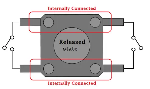
Button wiring
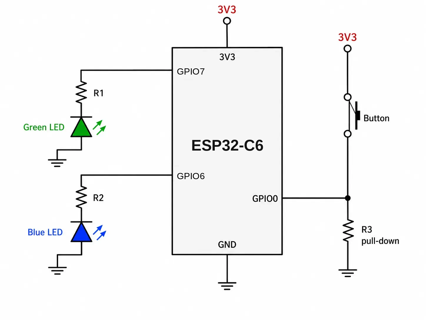
Complete diagram showing how to connect both LEDs (GPIO6, GPIO7) and the button (GPIO0) to the ESP32-C6-DevKitC-1.
- Build, flash, and monitor
Use the USB port labeled UART for flashing and for the monitor. Erasing flash (Erase Flash) before you flash this example is safe.
What should happen…
After flashing, the green LED should blink once a second, with this output:
In active mode
Long press the wake button to put the chip to sleep and run the ULP
A long press on the button starts the LP core and puts the HP core into deep sleep. The blue LED then blinks once a second, with this output:
Entering Deep-sleep mode
Press the wake button at least 3 or 4 times to wake up the main CPU again
Four clicks of the button wake the chip from deep sleep:
ULP woke up the main CPU!
In active mode
Long press the wake button to put the chip to sleep and run the ULP
Power is measured on the J5 header with a suitable tool, for example a JouleScope or a PPK2.
Blinking the LED from the HP core
With the “big” HP core doing the work, average consumption over 10 seconds is about 22.32 mA.
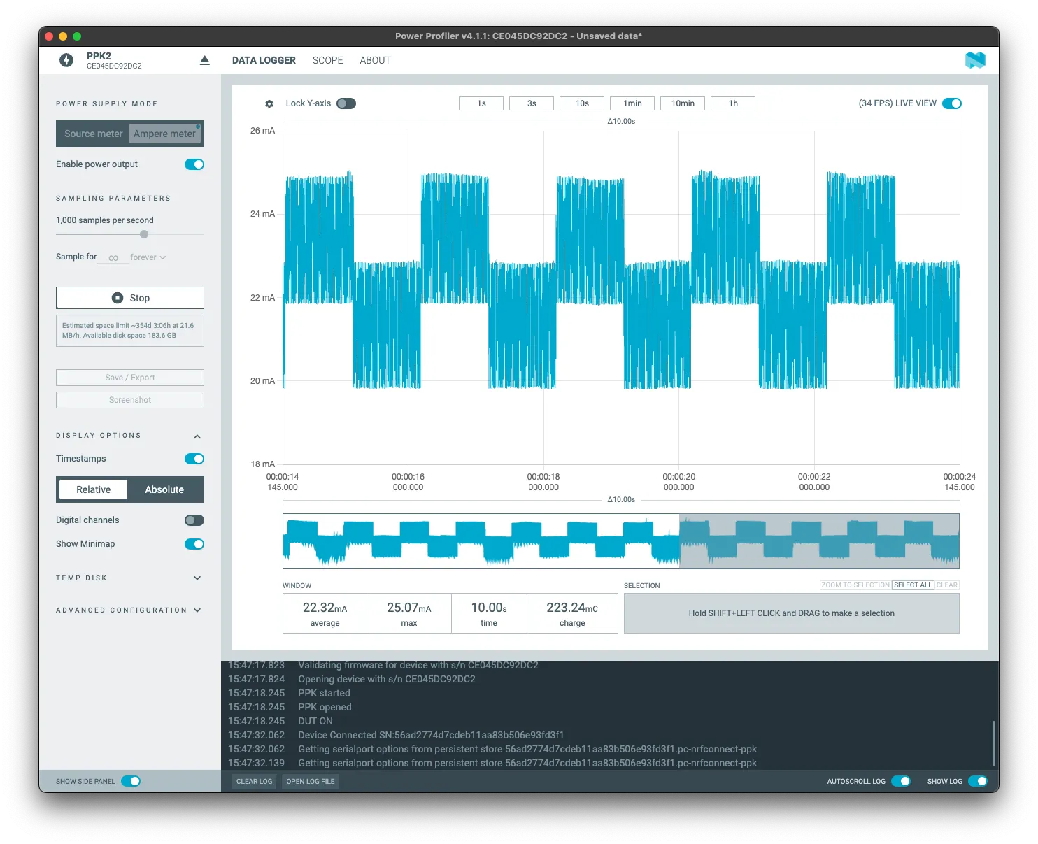
Blinking the LED from the LP core
Moving the same job to the LP core drops that by about an order of magnitude, to 2.97 mA.
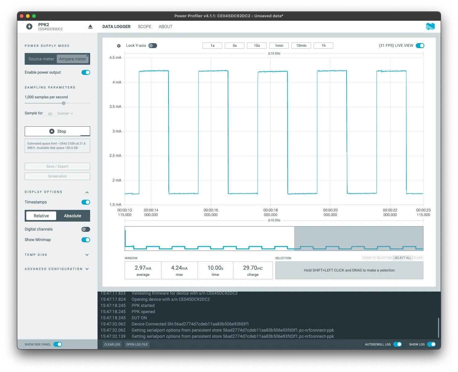
Switching cores saves up to 86.7% for the same task. Treat the numbers as a guide; real results will differ.
More LP core examples:
- LP Core simple example with GPIO Polling
- LP Core Pulse Counting Example
- LP-Core example with interrupt triggered from HP-Core
- LP I2C Example
- LP UART Examples
Conclusion
Thank you for taking part in the workshop. We hope it was useful.
Along the way we covered:
- Assignment 1: Installed ESP-IDF and learned the basics of using it.
- Assignment 2: Created a project, learned what components are, and used one to light the onboard LED.
- Assignment 3: Connected to Wi-Fi with BLE provisioning.
- Assignment 4: Tried an OTA update and the partition table.
- Assignment 5: Built an ESP-NOW chat room.
- Assignment 6: Ran code on the LP core and learned how to control power consumption.
That is still only a skim of the surface. Both the ESP32 and ESP-IDF offer much more. We hope the workshop gave you a solid base to keep building your own projects on.
Thank you again, and we look forward to your projects.